An on-board equipment need a 24v to 75V dc boost high voltage power module, the first set of discrete design scheme of power supply design formality, integration is poor and lack of practical verification, leads to unreliable power supply protection, key technical indicators do not meet the design requirements. In improving design work, we adopted the mature technology of high reliability of the DC/DC module to complete the design. A single DC/DC module maximum output voltage is commonly + 48 v, to get a higher output voltage, must use the module of input and output isolation characteristics, adopt the method of module series. Due to the power input voltage of + 24 V, so this design USES three modules in series to get 75 V. DC/DC switched power supply output impedance is extremely low, even three modules in series the serial output impedance is negligible relative to the load.
1.design construction and working principle
This design by PAF600F24-28 core power module , with the input parallel output series, realize dc 24 v to 75 v voltage conversion. Use an external potentiometer can adjust output voltage, within a certain range output voltage can be in - 60% + 60% of nominal value within the scope of adjustment. A single module has the highest output voltage adjustable, 110% to 28 V = 30.8 V, the minimum output voltage adjustable, 60% to 28 V = 16.8 V. Such three modules in series can get a wide output voltage range: 50.4 V boast is 92.4 V. When the three modules output adjust to 25 v can make the 75V. then the output current is 600 garment = 24 25 A. At the same time the booster power also has the start voltage monitoring and control, over-current, over-voltage, overheating, etc protection functions, to ensure safety and reliable power supply working. Three modules in series working principle in figure 1

figure1 Three modules in series working principle
Figure 2 for the application of a single power supply module circuit, the input electrolytic capacitor C1 for energy storage capacitor, can absorb module at the input voltage peak at the same time.C2 and C3 as common mode filter capacitors, using 2 kv high-voltage ceramics capacitors.D1 for transient absorption diode TVS, impact on the voltage transient and impact protective inhibitory effect, can prevent the power supply module is damaged while the occurrence of the transient pressure peak, TVS also have electrostatic protection function, to ensure that the module of work safety is great significance. In addition, use insurance tube can prevent the input unexpected reverse the damage module.
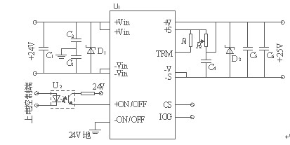
figure2 single power module application circuts
1.1 solution comparison
Figure 3 for booster power principle of discrete element program block diagram. The solution requires each function unit shall be a separate design, the whole design integration is quite low. Especially for isolation step-up transformer and power conversion circuit H bridge, as not very special design, only the conventional product, cause the volume is too big, and the whole design without sufficient aging test and validation of the actual work, which often requires to pass through many times repeatedly modification and perfect to meet the design requirements, not only time-consuming and also inefficient. In a DC/DC power supply switching module, power transformer and H power special form of bridge are designed to be flat, integrated in the module encapsulation, saved a space greatly. And power supply module technology already quite mature, high reliability, the designer just certain peripheral module as the core design, reasonable use of modules in series, in parallel technology, according to the design demand booster or power expansion, satisfy the requirement of technical indicators can be designed, good performance of work highly reliable integrated power supply. Compared with the discrete scheme, shorten the design cycle, greatly improve the reliability and technical indicators.
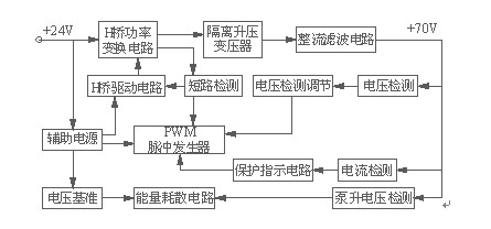
figure 3 Booster power principle of discrete element program
1.2 Membrane filter technique
Used in the module at the input common mode choke is very effective in membrane filter in circuit, under the effect of common mode interference signal, the choke on flux produced by the two coil in the same direction, reinforce each other, each coil inductance value is twice as many exist alone. So for power produced by high frequency common mode noise, choke the equivalent impedance is high. Therefore, common mode choke coil to common-mode interference has a strong inhibitory effect, and presents a low impedance, current differential mode and minimal loss of dc current to useful. Another effective method to reduce common-mode interference is to join the bypass capacitor, as shown in figure 2, C2, C3, used to bypass the common-mode current, to reduce the noise between the input line, at the same time also can absorb the input voltage surge.C2, C3, choose 4700 pf / 2 kv high-voltage ceramics capacitors. To prevent interference, introduced parasitic inductance, capacitance pins should be short as far as possible
2.Protecting function design and electromagnetic compatibility measures
In figure 1, D1, D2 and D3 for fast recovery diode, all the protection devices in series, function is to prevent the reverse voltage with any power supply module, D1, D2, D3, reverse pressure is more than twice the rated output voltage, electric current is more than twice the rated power output current, to the pressure drop should be small as far as possible.
In figure 2 ,D1, D2 for TVS diode (surge voltage absorber), TVS has a very short response time and high surge absorbing ability, can suppress transients voltage, as a result of the inductive load when switching voltage, can also be used to protect equipment or circuits from electrostatic and induction lightning over-voltage generated by the impact. TVS to protect the power system is in the bypass absorption way, and reduce the electromagnetic interference, and improve the power system reliability and life. Using TVS diode breakdown voltage is 10 yu higher than by working being protection voltage, in order to prevent the breakdown voltage circuit working voltage close to TVS, causing a leakage current TVS and affect the normal work of the circuit; Also can avoid the TVS to fall into line breakdown voltage caused by environment temperature change working voltage range.
Add filter capacitance on the module output voltage adjustment end will help to reduce the ripple. Through the power supply system is to adjust the end and output end polyester capacitor filter, power within various filtering measures such as using twisted-pair go line, eventually making + 75 v power supply output ripple control in 400 ~ 600 mv, met the 75 v power supply ripple voltage chest 750 mv using requirement.